🔥 Free Monthly Webinars (30 minutes): Check out the schedule! Extremely Popular (Don't miss out) 🔥Learn More

Hydrant System Block Plan

Australian Standard AS 2419.1 sets out the requirements for the system design, installation and commissioning of fire hydrant installations. The Standard also sets out specific requirements for a block plan to communicate the baseline data including system design, installation and performance criteria.

Fire Hydrant System Block Plan

A fire hydrant system block plan is a document and form of baseline data that provides information to first responders, building owners, managers and maintenance providers to communicate important aspects of the design, operation and location of a fire hydrant system. A block plan is typically A3 (297mm x 420mm) or greater in size so as to effectively communicate its contents and the fire safety features of a building.

A copy of the block plan is typically mounted at the booster assembly for the fire hydrant system and where constructed a second copy located at the fire control room or centre within the building.

A block shall be suitably protected so they remain clearly legible, fade and water resistant and resist deterioration from ongoing handling and use.

The Ultimate Fire Hydrant System Maintenance Checklist

Don't be confused by the industry language that a "hydrostatic test" is the same as the "five-yearly service"... it's not, the five-yearly service is much, much more than just a hydrostatic pressure test! Request a FREE copy of our Ultimate checklist to conducting a Fire Hydrant System 5-yearly maintenance.

Specific Features of a Fire Hydrant Block Plan

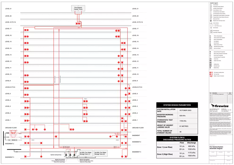
In addition to the typical features of a block plan, a hydrant block plan also includes additional information including;

  • the size and location of the water supply authority mains, including street hydrants incorporating dimensions;
  • water supply valves and connections for non-industrial purposes;
  • location and size of on-site fire mains;
  • location and capacity of water storage tanks or static water supplies;
  • location of each fire water pump;
  • location and total number of each fire hydrant landing valve;
  • location of each fire hydrant booster connection and assembly;
  • location of each water supply isolating valve, check valve and non-return valve;
  • location and description of any connection to other installed fire protection system or systems;
  • the required operating pressure (kPa) and flow rate requirement (L/s) of each system;
  • the location of the main electrical switchboard room;
  • the location of any fuel source including LPG tanks and each gas shut-off valve;
  • location of each flammable storage area

Additional baseline data that is required on a fire hydrant system block plan includes the following;

  • the name of the installing contractor or contractor that has subsequently modified the fire hydrant system;
  • the standard of performance (including year of publication) to which the system was designed, commissioned and subsequently tested;
  • the height of the highest fire hydrant valve for each hydrant pressure zone (main or ring main) above the lowest booster inlet connection.